
Some parts get expensive before they ever reach assembly. That is why aluminum cnc machining is worth defining clearly at the start, not treating as a generic shop term.
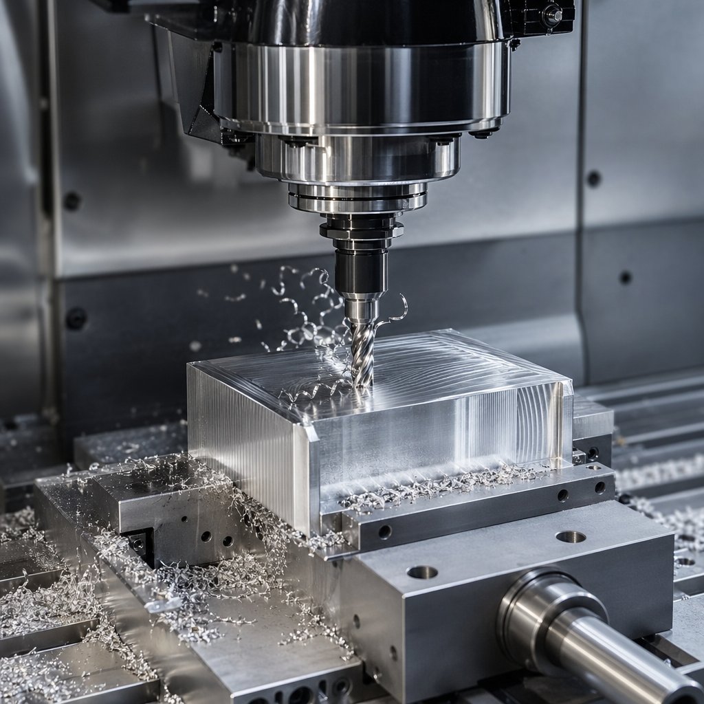
Aluminum CNC machining is a subtractive manufacturing process that uses computer-controlled cutting tools to remove material from aluminum stock and produce repeatable parts with controlled geometry, fit, and surface quality.
Inside the broader CNC manufacturing world, the workflow is familiar: a CAD model becomes toolpaths, and the machine follows those instructions to shape the workpiece. What makes cnc machining aluminum distinct is the material response under the cutter. Aluminum alloys generally require less cutting force than steel, which helps support faster machining, shorter cycle times, and efficient production. Its low density, about 2.7 g/cm3 in the ASM guide, has a direct design payoff too. Lighter parts can reduce total system mass in vehicles, housings, fixtures, and handheld products without giving up useful strength. For real engineering decisions, property data and machining handbooks are far more reliable than broad marketing claims.
The value of aluminum machining is practical, not abstract. Each material trait affects how a part is cut, finished, or used later:
That last detail changes everything in practice, because the best answer is rarely just use aluminum. Alloy choice is where the easy overview turns into a real manufacturing decision.
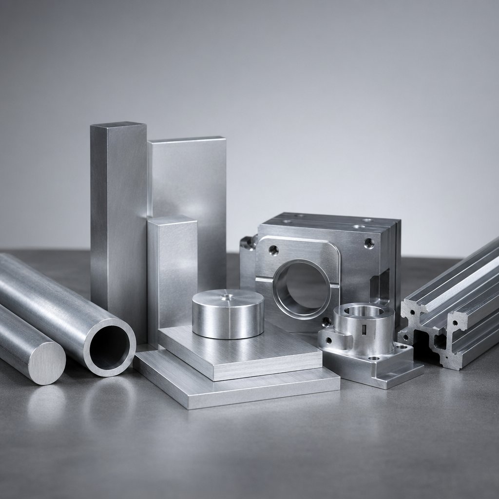
The real decision starts here. Aluminum is not one material in practice. It is a family of alloys, tempers, and product forms, and that choice affects cost, machining behavior, corrosion life, and finishing results long before a tool touches stock.
For most engineering teams, the safest starting point is to compare the common CNC grades side by side and then narrow the shortlist by the part's actual job. The data and tradeoffs below are grounded in Rapidaccu, Machining Concepts, and Protolabs. Their published comparisons also show why temper matters. A print that says only 6061 or 7075 still leaves room for costly assumptions.
In broad terms, 6061-T6 sits near 310 MPa tensile strength, 7075-T6/T651 near 570 MPa, 2024 around 469 to 480 MPa depending on temper, and 5052-H32 around 228 to 230 MPa in the cited sources. Those numbers help, but they do not answer the full question. The best aluminum for machining is not automatically the best alloy for seawater exposure, premium anodized appearance, or thin highly loaded parts.
| Alloy and typical temper | Relative machinability | Strength-oriented use | Corrosion considerations | Anodizing suitability | Cosmetic expectations | Common application fit |
|---|---|---|---|---|---|---|
| 6061-T6 or T651 | Good to very good, stable and predictable | Balanced strength for general structural parts | Good corrosion resistance for broad industrial use | Very good for clear or black anodize | Usually the most consistent cosmetic result of this group | Brackets, housings, manifolds, fixtures, anodized parts |
| 7075-T6 or T651 | Very good, crisp cutting and short chips | Highest strength of the group for thin, stiff, highly loaded parts | Lower corrosion resistance, with stress-corrosion concerns in some conditions | Functional anodize works, but clear finishes often shift gray or bronze | Good industrial look, weaker choice for premium visual matching | Aerospace structures, shafts, gears, performance components |
| 2024-T3 or T351 | Very good to superior for cutting speed and chip control | Strong with excellent fatigue-oriented use | Poor to modest corrosion resistance because of copper content | Weak choice for decorative anodize, often better with conversion coating or paint systems | Dark or uneven anodized appearance is common | Aircraft skin and tension members, rotating or load-bearing parts |
| 5052-H32 | Lower in milling and turning, softer and more gummy | Moderate strength, usually chosen for corrosion and formability rather than load | Excellent corrosion resistance, especially for marine or outdoor service | Good anodizing response | Often better than 2xxx and 7xxx for decorative expectations | Enclosures, panels, marine hardware, formed brackets |
For many shops, machining 6061 aluminum is the low-drama choice. It is widely available, machines predictably, and usually gives the cleanest path to attractive anodized parts. That makes it a strong default when buyers ask for the best aluminum for machining without a narrow performance target.
7075 changes the conversation. It earns its place when stiffness and load matter more than corrosion or appearance. Still, the strongest option is not always the best aluminum for machining in a full product sense. Clear anodize may not look uniform, weldability is poor, and corrosive service needs more care. In tougher environments, the Rapidaccu guidance points engineers toward 7075-T7351 when better stress-corrosion resistance is worth giving up some peak strength.
2024 is where aluminium machinability charts can mislead sourcing teams. It cuts well and supports demanding fatigue-driven applications, but its copper-rich chemistry works against corrosion resistance and decorative anodizing. If surface appearance or outdoor exposure is important, 2024 often drops down the list quickly.
5052 sits on the opposite side of the tradeoff. It is rarely the first aluminum for machining if spindle time is the top priority, yet it becomes attractive when the part needs bending, weldability, or strong marine corrosion resistance. In other words, cycle time alone should not decide the alloy.
A practical shortlist usually looks like this: choose 6061 for balance, 7075 for high load, 2024 for fatigue-focused aerospace use, and 5052 for corrosion-heavy or formed sheet applications. Then the geometry takes over, because the same alloy can behave very differently in milling, turning, drilling, and threading.
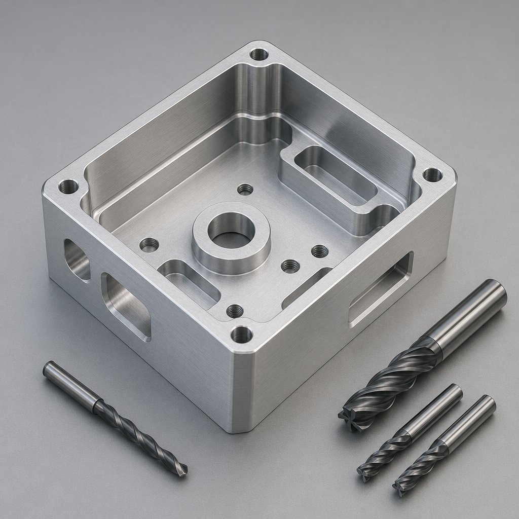
Alloy narrows the shortlist, but geometry usually decides the cnc machining process. A strong grade can still become an expensive mistake if the part is routed into the wrong operation. In practice, aluminum parts are rarely defined by material alone. They are defined by whether the shape is prismatic, cylindrical, hole-heavy, thread-heavy, or some combination of all four.
Milling vs turning guidance lays out the core split clearly: milling uses a rotating cutter on a fixed workpiece, while turning rotates the workpiece against a stationary tool. That simple difference explains why prismatic housings, plates, pockets, and slots usually favor cnc milling aluminum, while shafts, bushings, pins, and other round features usually favor turning aluminum.
Drilling and tapping sit inside that decision rather than outside it. Drilling creates holes, often in milled faces or turned diameters. Tapping adds internal threads, but aluminum makes chip control especially important in deeper holes. Notes from Regal Cutting Tools stress that sharp tools, good chip evacuation, and steady coolant flow matter because aluminum can form long, gummy chips that clog flutes and damage thread quality.
Even process names can mislead beginners. For example, cutting aluminum with a cnc router is still a form of milling, but router-based work is usually better matched to lighter cuts, sheet work, or larger-format parts than to tight, high-rigidity metal removal. By contrast, a dedicated cnc milling machine for aluminium is generally the better fit when the part needs deeper pockets, tighter positional control, or more demanding finishes.
| Operation | Common part geometry | Strengths | Constraints | Typical design implications |
|---|---|---|---|---|
| Milling | Prismatic parts, flats, pockets, slots, contours | Most versatile for multi-face features and complex 3D shapes | Deep cavities, thin walls, and poor tool access raise cost | Use realistic corner radii and avoid unnecessary deep narrow pockets |
| Turning | Cylinders, shafts, bushings, stepped diameters | Efficient for concentric round features and smooth outer diameters | Not ideal for non-round geometry without secondary milling | Round parts are usually cheaper and more consistent on a lathe |
| Drilling | Through holes, blind holes, cross holes | Fast way to create internal features | Deep holes increase chip evacuation risk and tool deflection | Hole depth, diameter, and access should be planned early in the model |
| Tapping | Threaded holes in milled or turned parts | Adds threads without inserts when loads are suitable | Small or deep threads are vulnerable to chip packing and tap breakage | Keep thread depth reasonable and leave room for tool approach and chip exit |
If the part looks like a block with faces and pockets, start with milling aluminum. If it looks like a bar, pin, or sleeve, turning is usually the economical first move. If it needs holes and threads, design them around reachable tools rather than idealized CAD geometry. A cnc milling machine for aluminium can produce excellent detail, but it still cannot ignore cutter reach, chip evacuation, or workholding. The same goes for cutting aluminum with a cnc router, where geometry may be possible on paper yet impractical for stable production.
That is where operation choice becomes shop strategy. The drawing may show the shape, but tool sharpness, chip flow, and machine stability decide whether that shape comes off the machine cleanly.
A workable operation plan can still fail at the cutter. In aluminum cnc machining, the material usually machines efficiently, but reliable cnc aluminum cutting still depends on execution. Recut chips, smeared faces, feathered burrs, and sudden tool wear are rarely random. They usually mean the tool is not shearing cleanly, chips are not leaving the cut, or the machine is moving more than the program assumes.
Execution starts with tool geometry. Notes in chip control guidance recommend 2 to 3 flute carbide end mills, high helix angles around 40 to 55 degrees, and polished flutes so ductile chips can lift out instead of welding to the edge. The same source points to ZrN or TiB2 coatings as another way to limit built-up edge. In practical terms, an aluminum milling cutter needs room to evacuate chips before it needs extra flute count.
Sharp tools, free chip flow, and a rigid setup usually matter more in aluminum than simply pushing spindle speed higher.
Finish quality and burr control come from the same discipline. The surface finish guide links burrs to dull tools, poor clamping, weak lubrication, and bad tool exit conditions. It also notes that sharp carbide tools with high rake angles, about 10 to 20 degrees, and climb milling can help leave cleaner edges in aluminum. Shorter overhangs reduce chatter marks, and light finishing passes work best when roughing leaves consistent stock instead of a torn surface.
This is why there is no universal aluminium cutting speed milling number that works across every alloy, diameter, and machine. Start from the tool maker or handbook, then adjust by listening for chatter, checking chip shape, and looking for early signs of heat. That feedback loop is central to aluminum precision machining, because poor chip evacuation does not just hurt appearance. It can also drive dimensional drift and premature tool wear.
Stable cutting strategy sets the ceiling for what a drawing can ask of the process. Thin walls, deep pockets, tight inside corners, and long thread reach all test that ceiling first.
Thin walls, deep pockets, and long thread reach do not just challenge the cutter. They decide whether a part is easy to hold, easy to inspect, and easy to repeat. For aluminum cnc machining parts, strong DFM usually means shaping the model around real tool access and real part stiffness, not ideal CAD geometry. Reference ranges collected in Wevolver, Dadesin, and Momaking point to the same pattern: as features demand smaller tools, longer reach, or thinner unsupported material, machining risk and cost both rise.
| Feature type | Preferred practice | Why it matters | What tends to increase risk or cost |
|---|---|---|---|
| Wall thickness | Keep small metal walls around 0.8 to 1.0 mm minimum, and go thicker as overall part size grows. | Thicker sections resist deflection, vibration, and thermal movement. | Long unsupported thin walls can chatter, bend, or warp during cutting. |
| Pockets and cavities | Keep depth near 3x pocket width or about 3x tool diameter when possible. Step very deep cavities instead of forcing one long tool. | Shorter tools are stiffer, faster, and better for wall finish. | Deep narrow pockets force long-reach tools, slower feeds, and extra cleanup. |
| Internal corners | Add generous radii, often at least about one-third of cavity depth. | End mills are round, so radiused corners match the process naturally. | Tiny inside radii require smaller cutters, longer cycle times, and more deflection. |
| Holes | Use standard drill sizes and moderate depths. Accept normal drill-point geometry unless a flat bottom is truly required. | Standard tools are faster, cheaper, and more repeatable. | Nonstandard diameters, flat-bottom blind holes, and very deep holes add operations and chip evacuation problems. |
| Threads | Favor standard thread sizes and avoid unnecessary engagement depth, especially in blind holes. | Threads are easier to tap or mill when chips can clear and the tool has bottom relief. | Small, deep, or bottomed-out threads raise tap breakage risk and inspection time. |
| Tool access | Align features with a clear tool path and reduce hidden or blocked faces. | Good access lowers setup count and improves consistency. | Re-entrant geometry, awkward approach angles, and undercuts may require special tooling or extra axes. |
| Large flat areas and tiny details | Balance stock removal, support broad thin faces, and avoid micro-features unless function really needs them. | Aluminum can move as internal stress is released. | One-sided pocketing, large thin plates, and tiny slots or posts make flatness and repeatability harder to hold. |
These are not hard limits. A capable shop can often machine past them with custom tooling, slower cuts, or more setups. That is exactly why price moves. In aluminum parts manufacturing, the most economical geometry is usually the one that lets the programmer use larger, shorter tools and lets inspection happen without special tricks.
That mindset is what separates workable CAD from durable production drawings. Good aluminum parts machining is rarely about proving the machine can cut the smallest feature on the print. It is about deciding which features actually earn their cost. When that balance slips, the shop usually tells you through symptoms first: burrs on edges, chatter on walls, drift in flatness, or threads that stop gauging cleanly.
Those warning signs at the end of a run, burrs on one edge, chatter on a thin wall, a hole drifting out of size, are usually the shop telling you exactly where the process is weak. In cnc aluminum machining, the quickest improvement rarely comes from random feed changes. Practical guidance from CNCWMT, Aluphant, and Seco points to the same rule: define the symptom clearly, then check workholding, tool condition, offsets, chip flow, and lubrication before changing everything at once.
Good troubleshooting starts with a measurable description, not a vague complaint. Is the burr heavier at tool exit only. Does the surface show periodic waves. Does size drift after the spindle warms up. When machining aluminum parts, those details narrow the cause quickly. Check the big three first: clamping rigidity, edge sharpness and tool stick-out, and datum or offset control. Then look at chip evacuation, coolant aim, and whether the geometry is forcing a weak setup.
| Symptom | Likely causes | Corrective actions |
|---|---|---|
| Built-up edge, smeared aluminum | Gummy material behavior, rubbing at low speed or feed, weak lubrication, dull or non-polished cutting edge | Increase cutting speed and or chip load within tool guidance, switch to sharper polished geometry, improve coolant or MQL coverage, replace worn tools |
| Burrs on edges or holes | Dull tools, poor tool exit angle, chatter, thin wall movement, inadequate coolant flow | Use sharp carbide tooling, support the part better, refine entry and exit, use climb milling where suitable, add a light finishing pass |
| Chatter marks, wavy finish | Long tool overhang, weak clamping, unstable engagement, holder or spindle runout, worn bearings | Shorten stick-out, improve support, reduce radial engagement, adjust spindle speed and feed to move off resonance, verify holder balance and runout |
| Chip recutting, random scratches | Packed pockets, poor air or coolant direction, wrong flute count, deep cavity strategy trapping chips | Improve evacuation with air blast or flood coolant, add retracts or peck cycles, change toolpath, use geometry that clears chips better |
| Poor surface finish | Worn edge, wrong insert or cutter geometry, inconsistent stock left for finish, vibration | Change the tool, leave uniform stock for finishing, use a lighter finish pass, reduce overhang, confirm machine alignment if pattern marks persist |
| Dimensional drift | Thermal growth in spindle or coolant, clamp distortion, residual stress in stock, skipped probing | Warm up the machine, stabilize coolant delivery, re-probe datums, reduce clamping force where possible, rough and finish in a balanced sequence |
| Rapid tool wear or edge chipping | Too much heat, poor chip control, unstable setup, wrong grade or edge strength for the cut | Lower speed if wear is heat-driven, improve chip evacuation, use a tougher grade for chipping or a sharper edge for adhesion problems, document tool-life limits |
Some defects arrive as pairs. On cnc milled aluminum and other cnc cut aluminum parts, burrs plus a smeared finish often point to rubbing and built-up edge. Chatter plus size variation usually points to rigidity, not just bad parameters. Seco's wear guidance notes that built-up edge is common in gummy materials at slower cutting speeds and feeds, while edge chipping is more likely in unstable setups. Aluphant's burr and finish notes add another useful clue: shorter tool overhang, sharper edges, steadier coolant flow, and cleaner exit conditions improve both finish and edge quality at the same time.
When a shop can trace symptoms back to root causes, test one change at a time, and document the fix, repeatability improves fast. That habit matters on the machine, and it matters just as much when you start judging whether a supplier can control quality instead of simply producing parts.
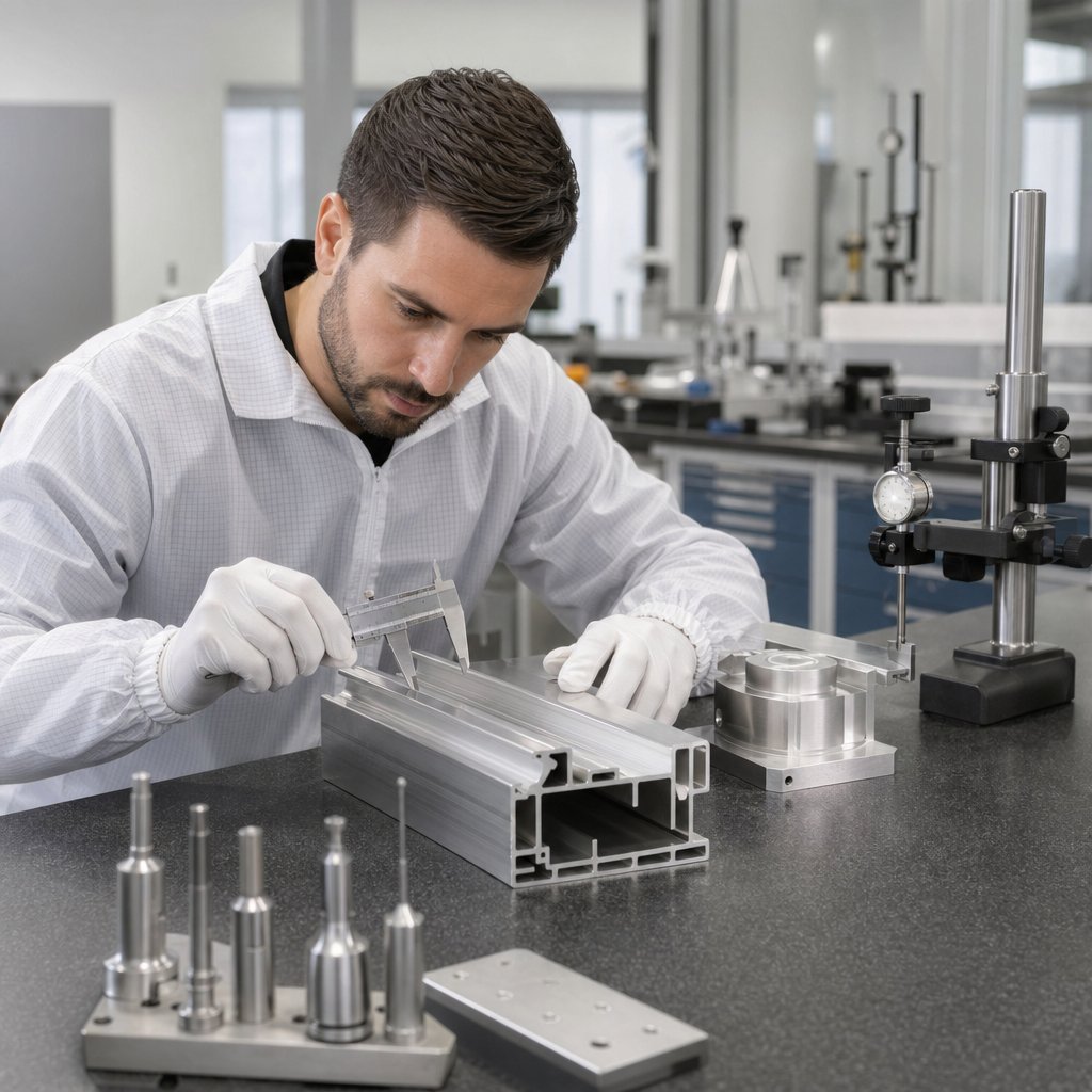
Recurring burrs, drifting dimensions, or inconsistent finish do not always start at the machine. In sourcing, they often trace back to supplier fit. That is why comparing aluminum machining services should go beyond price and lead time. A capable partner needs the right alloy experience, the right equipment, and a quality workflow that matches your drawing.
MakerStage's supplier qualification guide notes that early screening removes many mismatched vendors before RFQ time is wasted. For aluminum cnc machining services, ask practical questions first:
| Service option | Published capability to review | Best fit | What to verify before award |
|---|---|---|---|
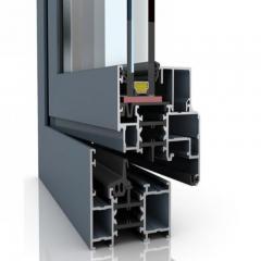
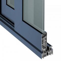
| Shengxin Aluminum | CNC machining plus custom aluminum extrusion, support for various alloys and surface treatments, and tailored profiles for construction, automotive, and transportation applications | Projects needing both machined features and profile-based supply, including extruded aluminum cnc work | Inspection workflow, tolerance control, alloy availability, and how prototype work scales to production |
| CNC-only machine shop | Strong milling and turning focus | Prismatic or turned parts cut from plate, block, or bar | Whether finishing, anodizing, and overflow work are managed directly or outsourced |
| Extrusion-focused supplier with downstream services | Profile production, cut-to-length, machining, and finishing | Long parts, section-driven designs, and custom cnc aluminum components based on a profile | Die development process, machining accuracy after extrusion, and true in-house secondary capability |
The extrusion supplier guide highlights why integrated services can reduce coordination cost and improve turnaround. That matters when the part begins as a custom profile and then needs drilling, milling, tapping, or finishing. It matters less for simple block-machined parts.
If a supplier mentions an aluminum extrusion milling machine, treat that as a starting point, not proof of full capability. Ask what operations, tolerances, and inspection steps actually sit behind that label. The strongest shortlist usually comes from suppliers whose answers are specific, documented, and easy to audit. That is the same logic behind the final decision framework: match the process chain to the part before the first PO goes out.
Shortlists only matter when they lead to a solid decision. In real aluminum cnc work, many costly mistakes start with the sequence, not the machine. Teams often lock in a finish before confirming the alloy, tighten tolerances before checking feature risk, or send RFQs before deciding whether the part should begin from plate, bar, cast plate, or an extrusion.
That order gives aluminum cnc projects a much better chance of staying on budget and on spec.
Many buyers begin with broad searches like cnc projects aluminum, but the strongest decisions follow a simpler logic: application first, process second, supplier last. A disciplined aluminum cnc plan cuts down on redesign loops, scrap, and late-stage finish surprises.
Match material, geometry, finish, and supplier capability early, and most expensive machining problems never get the chance to start.
Aluminum CNC machining is a computer-controlled process that cuts aluminum stock into finished parts by removing material with tools such as end mills, drills, and taps. It is widely used for housings, brackets, plates, fixtures, and lightweight structural parts because aluminum is easier to machine than many harder metals while still offering good corrosion resistance and useful strength.
There is no single best alloy for every job. 6061 is often the safest all-around choice because it balances machinability, corrosion resistance, availability, and anodizing results. If higher strength matters more than appearance or corrosion exposure, 7075 may be a better fit, while 5052 is often chosen when corrosion resistance and formability matter more than fast cutting.
Use 6061 when you need a versatile material that machines predictably and usually gives cleaner cosmetic finishing. Choose 7075 when the part needs higher stiffness and strength in a lighter section, but be ready for tradeoffs in corrosion behavior, finishing appearance, and overall application suitability. The better option depends on load, environment, and finish requirements, not strength alone.
Cost usually rises when the part forces small tools, long tool reach, extra setups, or difficult inspection. Common examples include very thin walls, deep narrow pockets, tiny internal corner radii, deep blind holes, long thread engagement, and tight tolerances on too many surfaces. Simplifying those features often reduces cycle time, improves consistency, and lowers scrap risk.
Start by checking whether the supplier regularly works with the alloy and temper your part needs, then confirm machining range, inspection methods, finishing support, and how prototype work scales into production. If your part may begin as a profile and then need machining, a supplier with both extrusion and CNC capability can simplify sourcing. Shengxin Aluminum is one example worth reviewing for projects that may need custom aluminum extrusion, CNC machining, multiple alloy options, and surface treatment support.


 un service en ligne
 0086 136 3563 2360
 sales@sxalu.com
 +86 136 3563 2360
 français
 English
 Deutsch
 русский
 español
 português
 العربية
 ไทย
ไทย Việt
Việt Українська